 donald
Installing a Lutron lighting control panel requires understanding three critical wiring connections: line voltage (120V or 277V), low-voltage control wiring, and neutral/ground paths. The installation process typically takes 2-4 hours for a competent DIYer with electrical experience, though hiring a licensed electrician is strongly recommended to ensure code compliance and safety. Success depends entirely on correctly interpreting Lutron’s color-coded wiring diagrams, which vary by model but follow consistent logic once you understand their symbology.
Lutron control panels have become essential components in modern smart lighting design driven by the surge in whole-home automation and energy management systems. According to recent lighting trends professional-grade dimming and scene control have moved from luxury installations into mainstream residential projects. This shift means more homeowners and installers encounter Lutron wiring diagrams without formal training in reading electrical schematics.
The challenge isn’t the physical wiring itself. It’s decoding what each terminal does, matching wire colors to diagram symbols, and understanding the difference between switched hot conductors and dimmed load wires. Lutron diagrams use standardized conventions, but small details like whether you’re wiring a RadioRA system versus a Homeworks QS panel create significant differences in terminal assignments and communication bus requirements.
This guide walks through diagram interpretation fundamentals, breaks down each connection type with clear explanations, and provides verification steps to confirm proper operation before energizing the system. We’ll address the most common wiring scenarios while emphasizing when professional assistance becomes non-negotiable.
Understanding Your Lutron Control Panel System
Before you attempt to wire any Lutron control panel, you need to understand which system you’re working with and how its components connect. Lutron manufactures several control panel lines, each designed for different scales and complexity levels.
Homeworks represents Lutron’s most sophisticated whole-home control platform. These systems use a central processor that communicates with individual dimmer modules and load controllers through dedicated low-voltage wiring. You’ll find Homeworks in larger homes and commercial installations where precise lighting control across dozens of zones matters. RadioRA 2 and RadioRA 3 systems eliminate much of the hard-wired communication network by using proprietary wireless signals between the main repeater and wireless dimmers, though the main panel still requires line-voltage wiring for power distribution. Caséta operates as Lutron’s entry-level wireless system, using a smart bridge rather than a traditional control panel, most Caséta installations involve individual smart switches rather than centralized panel wiring. Vive targets new construction and renovation projects where installers want wireless convenience with professional-grade performance.
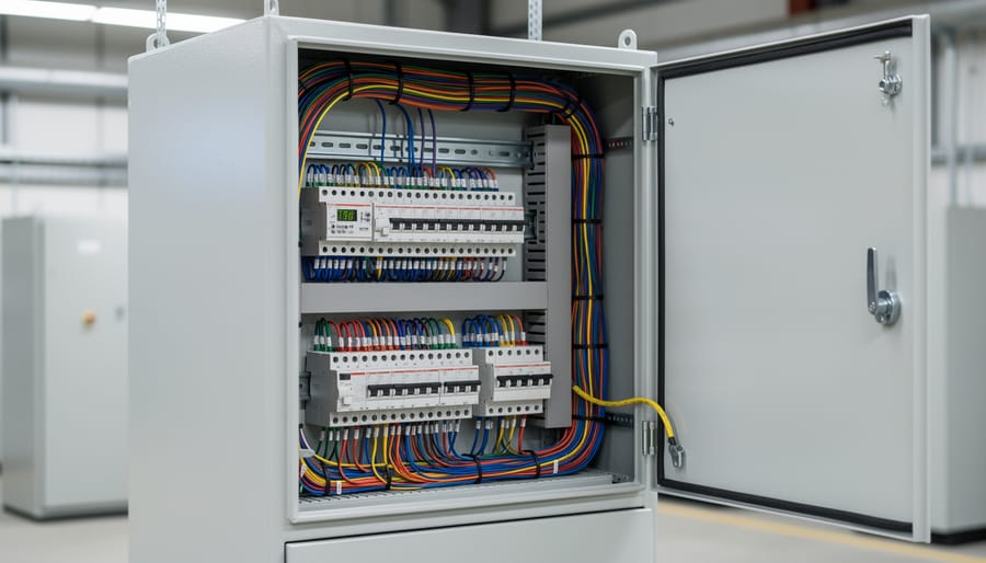
Every Lutron control panel system shares core components, though their arrangement varies. The main control panel or processor serves as the system brain, housing the logic and power distribution. Dimmer modules or load controllers regulate power to individual lighting circuits, these might plug into slots in the main panel (Homeworks) or exist as standalone devices (RadioRA). Line-voltage wiring carries 120V or 277V power from your breaker panel to the control system and out to your light fixtures. Low-voltage communication wiring connects keypads, sensors, and other control devices to the processor, typically using CAT-5, CAT-6, or proprietary Lutron link cables rated for 24V operation.
Understanding this architecture clarifies what you’ll see in wiring diagrams. When a diagram shows numbered terminals on a dimmer module, those represent load connections where circuit wires attach. Labels like “LINK+” and “LINK-” indicate low-voltage communication terminals. Color-coded wire paths distinguish between power delivery (line voltage in black, red, or blue) and control signals (communication wiring often in beige, gray, or paired colors). Most diagrams separate line-voltage and low-voltage sections with clear boundaries because mixing these creates both safety hazards and system malfunctions.
The specific terminology varies slightly between Lutron product lines, but this foundation applies across their control panel systems.
Tools and Materials You’ll Need
Before you start working with any Lutron lighting control panel, gather all necessary tools and materials. Having everything on hand prevents mid-project trips to the hardware store and ensures you can complete each step safely and efficiently.
Essential Tools
- Non-contact voltage tester, verifies power is off before you touch any wires
- Multimeter, measures voltage, continuity, and resistance for precise testing
- Wire strippers (10-22 AWG range), cleanly removes insulation without damaging conductors
- Screwdriver set (flathead and Phillips), for terminal connections and panel mounting
- Drill with appropriate bits, creates mounting holes and wire passage points
- Fish tape or pull string, runs wire through walls and conduit
- Label maker or write-on labels, clearly identifies all circuits and zones
- Wire cutters, trims conductors to proper length
- Flashlight or headlamp, illuminates work areas and panel interiors
- Torpedo level, ensures the panel mounts plumb and level
Required Materials
You’ll need 14 AWG or 12 AWG copper wire for line voltage connections, depending on your circuit breaker rating and local code requirements. Most Lutron installations use 14 AWG for 15-amp circuits. For low-voltage control wiring, stock up on 18 AWG stranded wire or CAT-5e cable, which varies by system type. Homeworks and RadioRA systems typically require specific communication cable, while Caséta relies on wireless connections with minimal hardwiring.
Stock wire nuts in assorted sizes, electrical tape, cable staples rated for your wire gauge, and appropriately sized junction boxes. If your local code mandates conduit for exposed wiring runs, purchase enough EMT or flexible conduit with the necessary fittings and connectors. A tube of dielectric grease helps protect outdoor or high-humidity connections.
Keep your specific Lutron wiring diagram and instruction manual within reach throughout the installation process.
Critical Safety Warnings Before You Begin
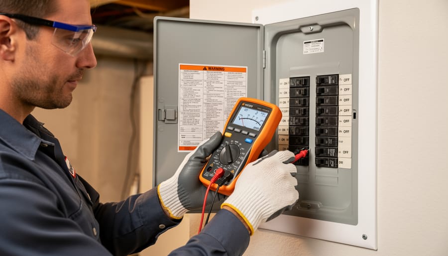
Working with electrical systems requires absolute attention to safety, before you touch any wire, you must understand the serious risks involved. Electrical current can cause severe injury, fire, or death, and cutting corners or skipping safety steps is never worth it.
After shutting off the correct breaker, use a reliable voltage tester at the panel location and on all wires you’ll be handling. Test multiple times and verify your tester is working by checking it against a known live circuit first. Lock out the breaker panel if possible and post a clear sign warning others not to restore power while you’re working.
You need to know when to stop and call a licensed electrician. If you’re uncomfortable working with line voltage (120V or 240V), uncertain about your local electrical codes, or dealing with complex three-way switching or multiple panel integration, hire a professional. Many jurisdictions require permitted work and inspections for control panel installations, check with your local building department before starting. Attempting work that requires a permit without one can create liability issues when selling your home and may void your homeowner’s insurance if something goes wrong.
Improper wiring doesn’t just risk immediate shock, it creates ongoing fire hazards from loose connections, overloaded circuits, or incorrect wire gauge. These problems can smolder for months before igniting. Additionally, any installation that deviates from Lutron’s specifications will void your system warranty, leaving you unprotected if components fail. Lutron designs their wiring diagrams around specific safety standards; following them exactly isn’t optional.
Respect the electrical code requirements in your area, which exist to protect you and your property. The National Electrical Code (NEC) sets minimum standards, but local amendments may be stricter. When in doubt, consult a qualified electrician who understands both Lutron systems and your jurisdiction’s requirements, it’s a small investment compared to the cost of fixing dangerous mistakes.
Reading and Interpreting Your Lutron Wiring Diagram
Lutron embeds detailed wiring diagrams in the installation guide that ships with your control panel and publishes them in downloadable PDFs on their professional support portal. Start by confirming your exact model number, printed on a label inside the panel enclosure or on the original packaging, then download the installation manual specific to that model and firmware revision. Using a generic diagram for a similar-looking panel can lead to incorrect connections, so verify you have the right document before you touch a single wire.
Lutron diagrams follow electrical engineering conventions but add their own shorthand. Solid lines indicate line-voltage wiring (typically 120V or 277V circuits carrying power to fixtures), while dashed or thinner lines represent low-voltage control wiring (24V or data cables connecting keypads and processors). Terminals are labeled with alphanumeric codes, L for line (hot), N for neutral, GND for ground, and numbered outputs like DIM1 or LOAD2 for individual lighting zones. Color codes in the diagram usually match industry standards: black or red for hot, white for neutral, green or bare copper for ground, and various colors for low-voltage communication wiring similar to under cabinet wiring setups where multiple control runs are involved.
To follow the power flow path, trace the diagram from the incoming breaker connection through the panel’s main terminals, then out to each dimmer module or relay, and finally to the fixture loads. Lutron diagrams show this path with arrows or numbered steps, making it clear which circuit feeds which zone. Pay attention to any notes or callouts in the margins, these often specify wire gauge requirements, maximum distances for communication cables, or load capacity limits for each module. Understanding these conventions turns the diagram from a confusing schematic into a reliable roadmap for every connection you’ll make.
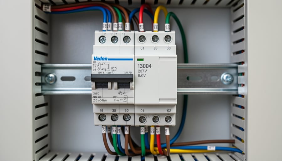
Step-by-Step Wiring Process
Step 1: Prepare the Installation Site and Power Supply
Start by choosing a location for your Lutron control panel that meets both code requirements and practical needs. The panel must be mounted in a dry, climate-controlled area with ambient temperatures between 32°F and 104°F. Allow at least 3 feet of clearance in front of the panel for service access and 6 inches on each side for wire management and heat dissipation.
Mount the enclosure to wall studs or a plywood backboard using appropriate fasteners for your wall type. The panel should sit at a comfortable working height, typically 4 to 5 feet from the floor. Ensure the mounting surface is level and can support the panel’s weight plus installed modules.
Before running power, verify your electrical service has adequate capacity for the added load. Install a dedicated circuit breaker sized according to the panel’s specifications, usually 20 or 30 amps depending on the system. Run appropriately sized wire from the breaker panel to your installation site using 12-gauge for 20-amp circuits or 10-gauge for 30-amp circuits.
Establish proper grounding by connecting the equipment grounding conductor to the panel’s ground bar and ensuring continuity back to your main service panel ground.
Step 2: Install the Main Control Panel and Modules
Begin by positioning the main control panel or processor in the prepared enclosure, ensuring proper orientation. Most Lutron panels mount on a DIN rail system, slide the panel onto the rail until you hear or feel it click securely into place. Check that it sits flush and level before proceeding.
Next, install your dimming and switching modules into the available slots according to your system design. Each module should align with the panel’s connector pins. Firmly press down until the module seats completely and engages the locking mechanism. Verify that module status indicators are visible and that nothing obstructs ventilation slots.
Leave adequate space between modules for heat dissipation, especially with high-wattage dimming modules. Consult your specific panel’s installation guide for minimum spacing requirements, overcrowding can cause thermal issues.
Before making any electrical connections, organize the incoming wires within the enclosure. Strip wire ends to the length specified in your diagram, typically ½ to ¾ inch. Group line voltage and low-voltage wires separately to prevent interference and maintain code compliance. This preparation makes the actual wiring process smoother and reduces errors during connection.
Step 3: Wire Line Voltage Connections
With the control panel and modules installed, you’re ready to make the line voltage connections that deliver power to your lighting loads. This step requires careful attention to wire sizing, terminal tightness, and electrical code standards.
Start by identifying your incoming line voltage feed from the breaker panel. Most Lutron systems accept 120V or 277V circuits, depending on your installation. Verify voltage with your tester before connecting any wires. The main panel will have clearly marked terminals for line (hot), neutral, and ground connections. Connect the incoming hot wire to the designated line terminal, typically marked “L” or with a brass-colored screw. The neutral wire connects to the neutral bus bar (silver terminals), and the ground wire attaches to the grounding bar or green screw.
Next, wire each load circuit to its assigned dimming module or relay. Each module has input terminals (receiving power from the panel’s bus) and output terminals (feeding your lighting fixtures). For reliable, code-compliant connections:
- Strip wire insulation 3/4 inch from the end, ensuring no nicked conductors
- Insert the bare wire fully into the terminal opening until copper is no longer visible
- Tighten the terminal screw firmly, give it an extra quarter-turn after initial resistance
- Gently tug each wire to verify it cannot pull free from the terminal
- Check that no stray wire strands extend outside the terminal block
Follow standard color conventions throughout: black or red for hot conductors, white for neutral, and bare copper or green for ground. If you’re using cable with different colors, clearly label each wire at both ends to avoid confusion during troubleshooting.
Pay close attention to polarity on dimmed loads. While standard on-off switching tolerates reversed connections, dimmers require the hot wire on the correct terminal for proper operation and safety. Double-check each connection against your wiring diagram before moving to the next circuit, and never assume wire colors are correct without verification.
Step 4: Connect Low-Voltage Control Wiring
Low-voltage control wiring creates the communication backbone between your Lutron panel and wall stations. Unlike the line voltage work you just completed, these connections carry data signals, not power, but precision still matters for reliable system operation.
Start by running the appropriate communication cable from the main panel to each keypad or sensor location. Homeworks systems use Lutron’s proprietary link cable (typically 18/4 or 18/5), while RadioRA 2 requires standard CAT-5 cable. Strip about half an inch of insulation from each wire end, keeping pairs twisted together until the last possible moment to minimize interference.
At the control panel, terminate link cables to the designated communication terminals on your processor or repeater. Most Lutron systems use screw terminals color-coded to match their wiring diagrams, red, black, yellow, and green are standard. Insert each stripped wire, tighten the screw firmly, and give a gentle tug to verify the connection holds.
For daisy-chain topologies, wire runs from keypad to keypad before returning to the panel. Star topologies run dedicated cables from each device back to a central hub. Consult your specific system’s wiring diagram to determine which topology applies. Keep control wiring at least six inches away from line voltage cables to prevent electrical noise, and secure runs every three feet with cable staples.
Step 5: Label All Circuits and Finalize Connections
After completing all wiring connections, create a comprehensive labeling system before closing the panel. Use a label maker or pre-printed circuit labels to mark every wire at both the panel termination point and at the load end. Each label should include the zone number, room location, and load type (e.g., “Zone 3 – Kitchen Pendants – LED”).
Document your zone assignments in a written schedule that matches your Lutron wiring diagram. Note the breaker number feeding each circuit, the dimmer module slot location, and the maximum load connected. Keep one copy inside the panel door and store a digital backup with your home maintenance records.
Organize wires within the panel using cable ties or wire management channels, separating line voltage from low-voltage control wiring. Route cables neatly to avoid strain on terminals and ensure the panel cover can close without pinching any conductors. Tuck excess wire length into available space rather than cutting it short, this flexibility proves invaluable during future troubleshooting or system expansion.
Proper labeling transforms a confusing tangle of wires into a logical system that anyone can understand during an emergency or upgrade, potentially saving hours of tracing circuits with a tester.
Testing and Verifying Proper Operation
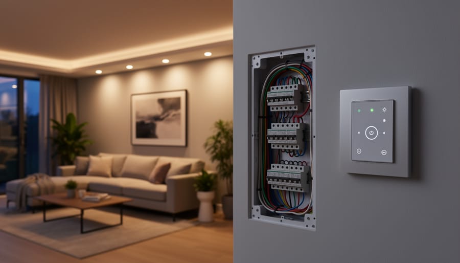
Before flipping the breaker back on, double-check every connection you made and confirm all panel covers are secured. Walk through your work systematically, verifying wire nuts are tight, terminals are properly seated, and no bare copper is exposed.
Turn the main breaker on, then energize the circuit feeding your Lutron panel. Use your non-contact voltage tester to confirm power is reaching the panel’s input terminals. You should see the panel’s power indicator light illuminate. If it doesn’t, stop immediately and verify your main power connections before proceeding.
With your multimeter set to AC voltage, test between line and neutral at the panel’s input. You should read approximately 120V for single-phase or 240V for split-phase systems. Next, check each load output terminal while the corresponding zone is switched on. The voltage reading should match your input voltage, confirming the relay or dimmer module is passing power correctly. Zero voltage at an output when the zone is activated indicates a faulty module connection or a defective component.
Test each lighting zone individually through the control interface. Turn zones on and off, listening for relay clicks and watching for immediate light response. For dimmed zones, slowly adjust from zero to full brightness. The lights should ramp smoothly without flickering, buzzing, or sudden jumps. Erratic dimming often points to incompatible bulbs, loose neutral connections, or a module exceeding its rated load.
Verify communication between the main panel and all keypads or wall stations. Press buttons and confirm the system responds as programmed. If a keypad doesn’t control its assigned loads, check your low-voltage control wiring connections at both the keypad and the panel terminals.
Before closing up your work, perform these final verification tests:
- Measure voltage at every zone output with loads energized
- Cycle each zone on and off at least three times
- Test full dimming range for every dimmable circuit
- Confirm all keypads communicate with the main panel
- Verify proper operation of any integrated sensors or timers
- Check that circuit labels match the actual connected loads
Common problems at this stage include reversed line and load wires, which prevent zones from turning on, and mixed neutrals between circuits, causing lights to glow faintly when off. If you encounter voltage readings significantly below expected levels, inspect for loose connections or undersized wire. Persistent communication failures between components usually trace back to improperly terminated CAT-5 cables or incorrect wiring topology for your specific Lutron system.
Document any anomalies you find and correct them before energizing the full system for extended use.
Programming and Next Steps After Installation
With your Lutron control panel properly wired and tested, you’ll need to program it to control your lighting the way you want. Basic systems like Caséta can be set up entirely through the Lutron app on your smartphone, typically taking 15-30 minutes to connect devices and create initial scenes. More advanced systems like RadioRA 2 or Homeworks require programming software that you’ll download from Lutron’s website, though these platforms offer significantly more customization for complex installations.
Start by registering your system at to activate your warranty and access technical support. The registration process requires your panel’s serial number and purchase date, and it unlocks firmware updates that improve system stability. Once registered, you can begin creating lighting scenes (preset combinations of light levels), scheduling automated adjustments based on time of day, and integrating with voice assistants or other smart home platforms.
For straightforward residential systems, the Lutron app’s guided setup walks you through naming zones, adjusting dimming curves for different fixture types, and programming wall stations. However, sophisticated installations with multiple rooms, integration with shades or HVAC systems, or commercial applications typically benefit from professional programming services. Many installers who specialize in lighting design software can program complex Lutron systems remotely once the wiring is complete.
Lutron provides extensive programming guides, video tutorials, and a technical support line specifically for DIY installers working through setup challenges.
Common Wiring Mistakes to Avoid
Even experienced installers occasionally make wiring mistakes that compromise Lutron control panel performance or create safety hazards. Understanding these common errors helps you avoid costly troubleshooting, system failures, and potential fire risks.
Using Incorrect Wire Gauge
One of the most frequent mistakes is choosing wire that’s too small for the circuit load. Undersized wire heats up under normal operation, eventually degrading insulation and creating fire hazards. Always match wire gauge to the amperage your circuit will carry, 14 AWG for 15-amp circuits, 12 AWG for 20-amp circuits. Check your dimming modules’ specifications, as some high-wattage zones require heavier wire even when the breaker allows smaller gauge. When in doubt, go larger; it’s safer and future-proofs your installation.
Making Poor Terminal Connections
Loose or improperly stripped wire connections cause intermittent operation, overheating, and potential arcing. Strip only enough insulation to reach the terminal without exposing bare copper beyond the connection point, typically half an inch. Tighten terminal screws firmly but avoid overtightening, which can damage the terminal block or break stranded wire. After tightening, gently tug each wire to confirm it’s secure. Connections should feel solid with no movement.
Mixing Neutral Wires Between Circuits
Shared or mixed neutrals between different dimming zones create erratic behavior and potential overload conditions. Each circuit requires its dedicated neutral return path to function correctly. This mistake often happens when installers assume all white wires connect to a common neutral bus without checking circuit separation requirements. Label neutrals as you install them, matching each to its corresponding hot wire and circuit number.
Improper or Missing Grounding
Skipping ground connections or using inadequate grounding wire puts users at risk of electrical shock and creates potential for equipment damage during power surges. The metal panel enclosure, mounting frame, and every component must connect to the grounding system. Use green or bare copper ground wires of appropriate gauge, and verify continuity between the panel ground and your main service ground.
Overloading Dimming Modules
Each Lutron dimming module has a maximum wattage rating that you must respect. Exceeding this limit causes the module to overheat, triggers thermal protection shutdowns, or leads to premature failure. Calculate the total wattage of all fixtures on each zone before connecting them. Remember that inrush current from some LED fixtures effectively increases their load, so leave a 20% safety margin below the rated maximum.
Ignoring Manufacturer Load Ratings and Compatibility
Not all Lutron dimmers work with every fixture type. Installing an incandescent-rated dimmer on an LED circuit causes flickering, buzzing, or complete failure. Check compatibility specifications for your specific fixtures, particularly LED and low-voltage lighting, and select the appropriate dimmer model. The wiring diagram indicates which modules belong in which slots, and reversing them compromises system performance even when physical connections seem correct.
Frequently Asked Questions
Can I install a Lutron lighting control panel myself, or do I need an electrician?
If you have electrical experience and understand your local codes, some Lutron systems support DIY installation. However, line voltage work requires a licensed electrician in many jurisdictions, and professional installation protects your warranty and ensures code compliance.
What type of wire should I use for Lutron control panels?
Line voltage connections typically require 14 AWG or 12 AWG copper wire depending on circuit load, while low-voltage control wiring uses CAT-5e or CAT-6 cable for most newer systems. Always verify gauge requirements in your specific wiring diagram, as undersized wire creates safety hazards.
Are Lutron control panels compatible with LED fixtures?
Yes, but you must use the correct dimming modules rated for LED loads. Standard incandescent dimmers can cause flickering, buzzing, or premature LED failure, so choose modules specifically designed for electronic low-voltage or forward-phase dimming based on your fixtures.
How do I expand my Lutron system after initial installation?
Most Lutron systems allow expansion by adding modules to available slots in the main panel or installing additional panels that communicate over the control network. Plan your initial installation with future growth in mind, leaving open module positions and spare low-voltage home runs.
What should I check first if a zone isn’t responding after wiring?
Verify power at the module using a multimeter, check that load wires are connected to the correct terminals, confirm the neutral connection is secure, and ensure communication wiring is properly seated. Loose connections account for the majority of non-responsive zones.
Do I need special training to work with Lutron low-voltage wiring?
Low-voltage control wiring is generally safer and simpler than line voltage work, but you should understand network topology and proper termination techniques. Lutron provides installation guides and support resources, though complex systems benefit from certified installer expertise.
Beyond these common installation questions, remember that modern lighting control systems represent a significant investment in your home or business. Taking time to wire the system correctly from the start saves frustration and prevents costly troubleshooting later. When facing installation challenges or questions not covered in manufacturer documentation, reaching out to Lutron technical support or consulting with an experienced integrator ensures your system performs reliably for years.
Successfully wiring a Lutron lighting control panel comes down to one non-negotiable principle: follow the manufacturer’s wiring diagrams exactly as specified. These diagrams aren’t suggestions, they’re engineered specifications that ensure your system operates safely and maintains your warranty coverage. Even small deviations can create functionality problems or safety hazards that won’t be immediately obvious.
If you’re uncomfortable working with electrical systems, lack experience with low-voltage wiring, or encounter a complex installation involving multiple panels and zones, hiring a licensed electrician isn’t just smart, it’s essential. The investment in professional installation pays dividends through proper system performance, code compliance, and peace of mind. Many homeowners find that hybrid approaches work well: handling the planning and layout yourself while bringing in a professional for the actual wiring and programming.
DonsBulbs Lighting Design specializes in Lutron system consultations, helping you select the right components for your space and providing installation support tailored to your project’s scope. Our team understands both the technical requirements and the design possibilities these systems offer. Contact us to discuss your lighting control goals and ensure your installation delivers the performance and reliability you expect.